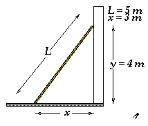
Solution: The forces acting on the ladder come from gravity, static
friction (the ladder is not moving), and contact with the floor and the wall.
Since no friction is acting at the wall, only the normal force, Fw, is acting there. At the floor, the static
friction magnitude is unknown because its value can be anywhere between 0 and
the maximum possible value of musFN. We note that we have chosen the angle theta
such that theta = arctan(3/4) = 37° and we have chosen the rotation axis for
calculation of torques to be perpendicular to the plane of the page and
passing through the point of contact between the ladder and the floor. Since
we want the translational and angular accelerations to be zero, we need the
net torque and net force to be zero, so

and
| x: | fs - Fw | = 0 ==> |
| fs | = Fw | |
| y: | FN - W | = 0 ==> |
| FN | = W = 60 Nt | |
| T: | Fw, pL - Wp(½ L) | = 0 ==> |
| Fwsin(theta) | = ½ Wcos(theta) ==> | |
| Fw | = ½ Wcot(theta) | |
| = ½ (60 Nt)cot(37° ) | ||
| Fw | = 40 Nt |
From our x equation of motion, we have fs
= Fw = 40 Nt.
Solution: All of our force diagrams will appear the same. The only
things that have changed is that now x and y no longer equal 3 m and 4 m,
respectively. However, it must still be true that (5 m)2 =
x2 + y2. Also, we see that the frictional force does
point to the right as we assumed in the force diagram for the previous
problem, so the static frictional force will have to go to its maximum value,
mus FN =
(0.3)(60 Nt) = 18 Nt, to keep the ladder from slipping. From our x equation of
motion, we have
To get the maximum distance of the bottom of the ladder from the wall, we
use the torque equation from the previous problem to determine the maximum
value of theta.
| Fw, max | = ½ Wcot(thetamax) ==> |
| thetamax | = arccot[2Fw, max/ W] |
| = arccot[2(18 Nt)/(60 Nt)] = 59° |
This maximum value of theta corresponds to a maximum distance from the wall
as follows:

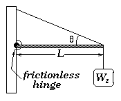
Solution: We draw the free-body diagram depicting all the forces and
torques acting.

The torques should be calculated around an axis perpendicular to the page
and going through the connection between the hinge and the beam. This
eliminates the need to find the torque due to the two unknown forces which the
hinge provides on the beam. For static conditions, the net forces and torques
must be zero, so
| x: | FNx - T cos(theta) | = 0 ==> |
| FNx | = T cos(theta) | |
| y: | T sin(theta) - FNy - W1 - W2 | = 0 ==> |
| FNy | = T sin(theta) - W1 - W2 | |
| torque: | (T sin(theta))L - W1(L/2) - W2L | = 0 ==> |
| T sin(theta) | = ½ W1 + W2 |
With T*sin(theta) known in terms of W1 and W2, we can find T as (½ W1 + W2)/sin(theta). We also have FNx = T cos(theta) = (½ W1 + W2)cot(theta) and
FNy = -½ W1
The minus sign indicates that we chose the wrong direction for FNy. This force actually points up rather than down. Keep in mind that the equations for force and torque will automatically indicate the correct directions for forces provide you are consistent in keeping track of signs.


Next: Angular Momentum Up: Completing the Circle Previous: Rolling Motion cont'd.
larryg@upenn5.hep.upenn.edu
Thu Jan 29 17:38:58 EST 1998 subsection4_1_5.html